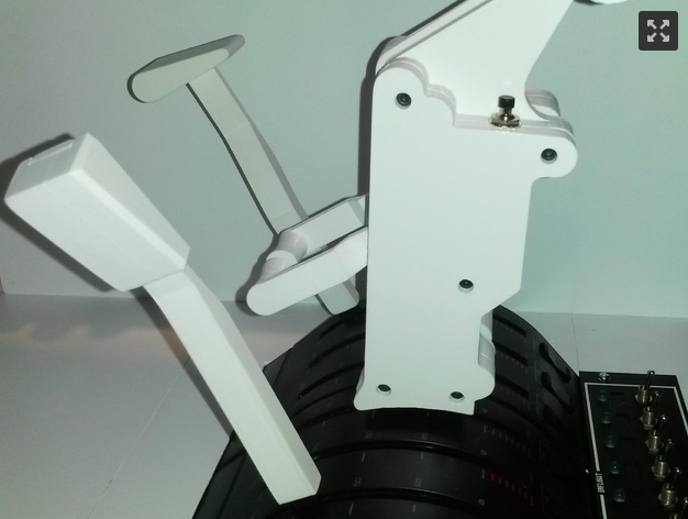
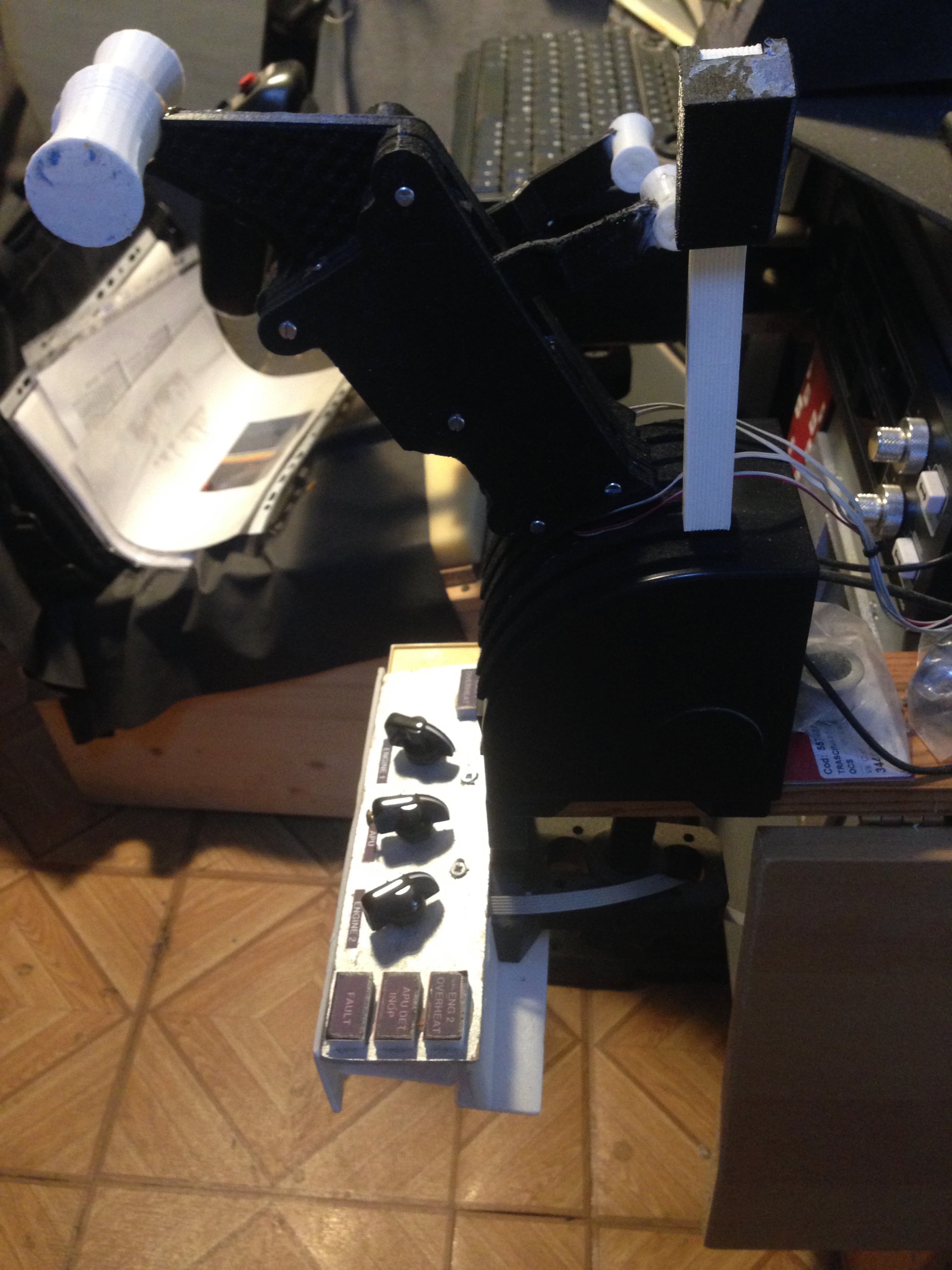
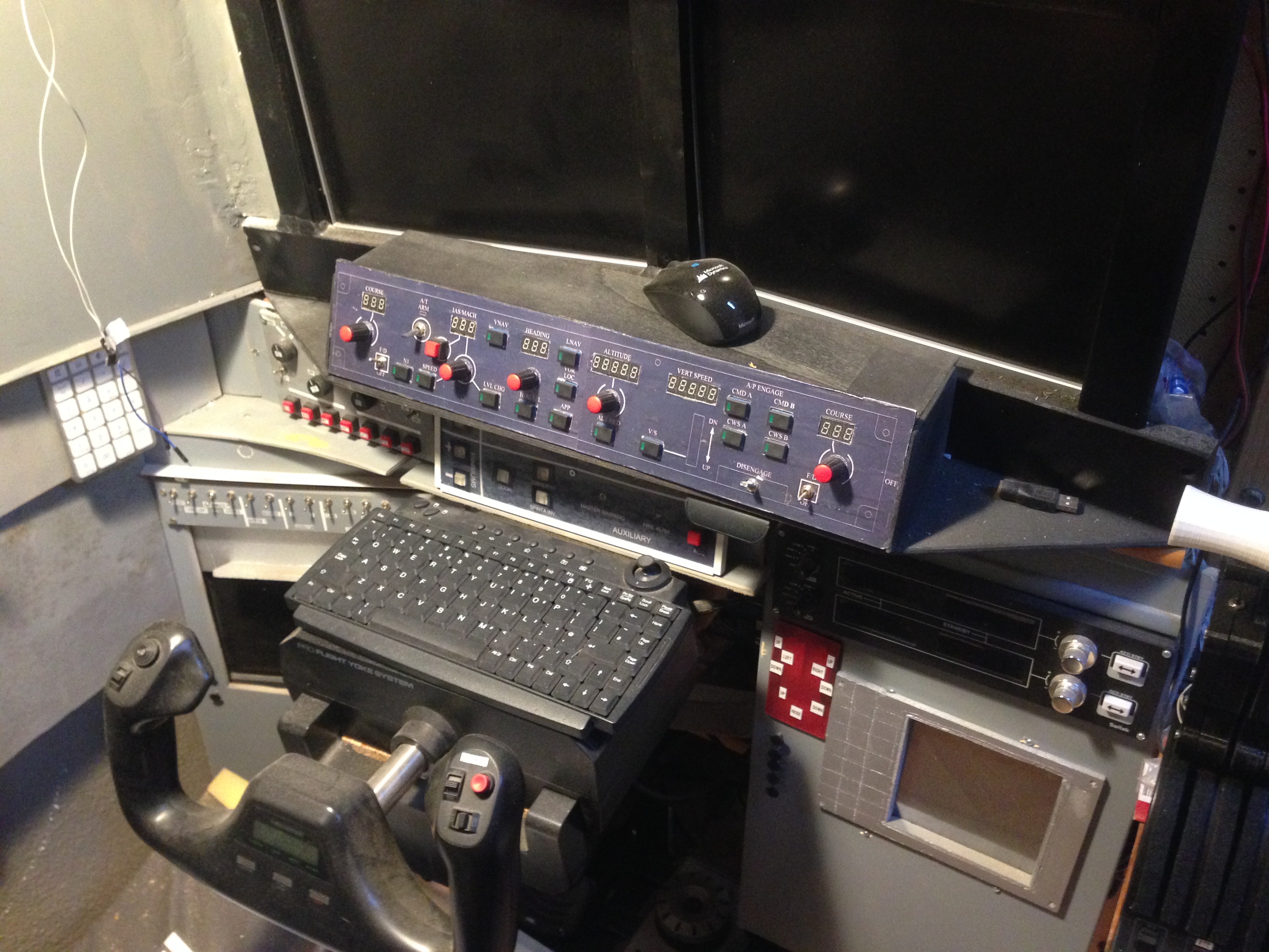
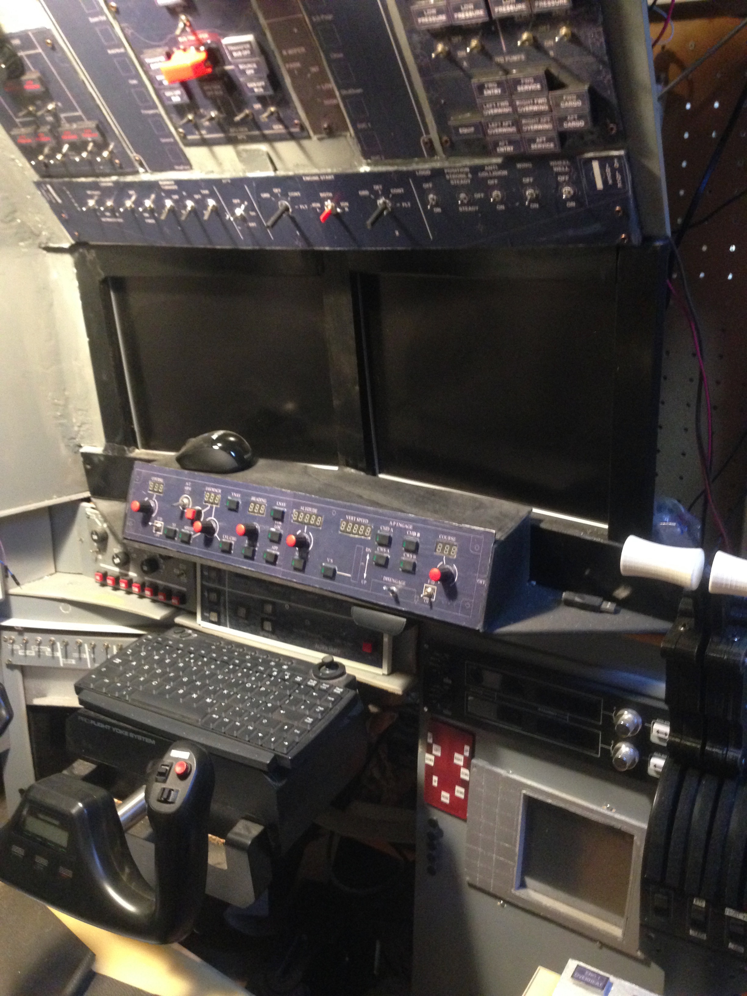
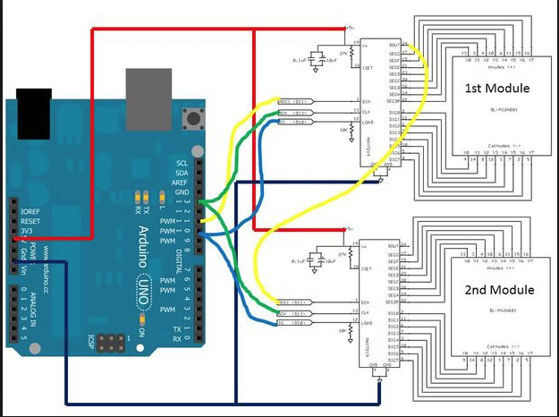
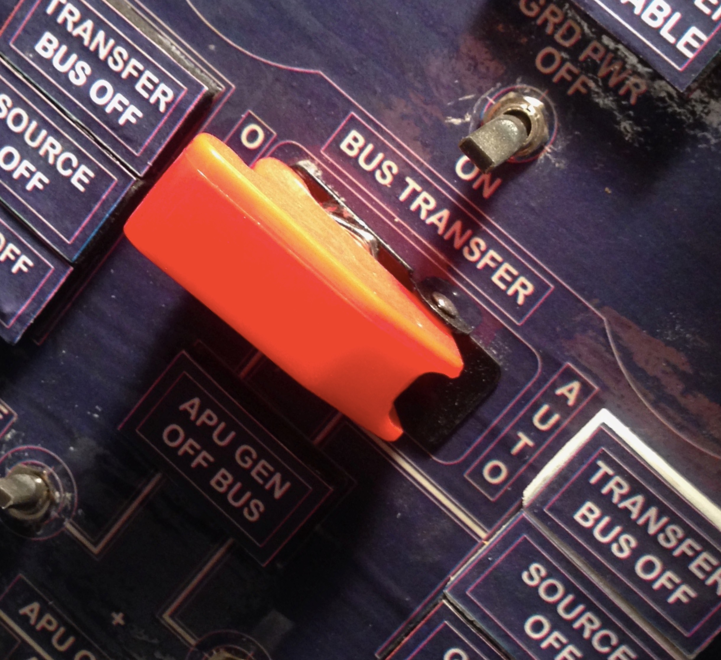
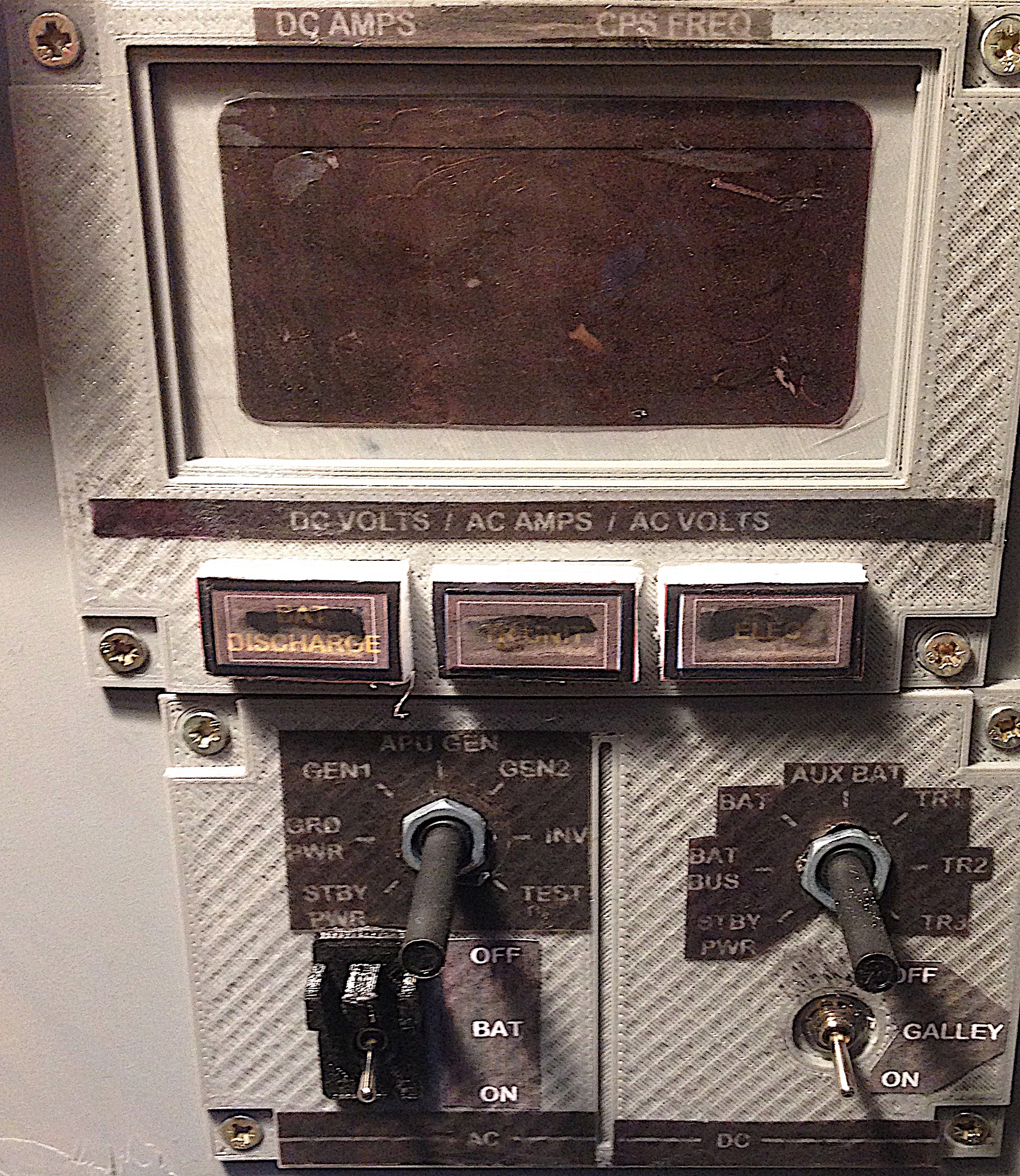
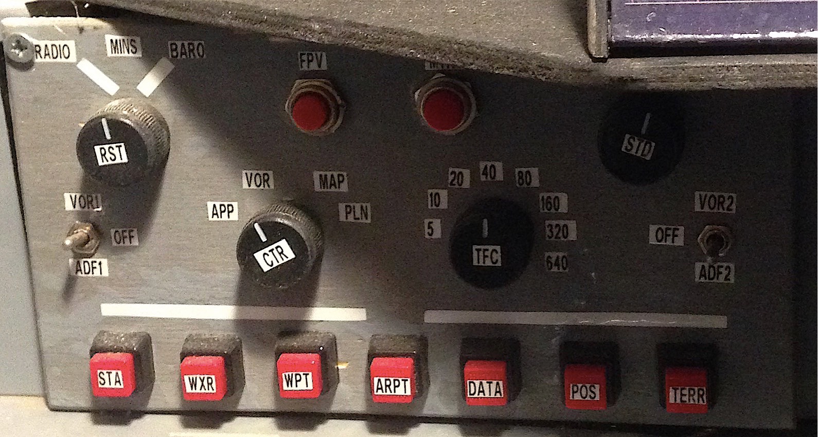
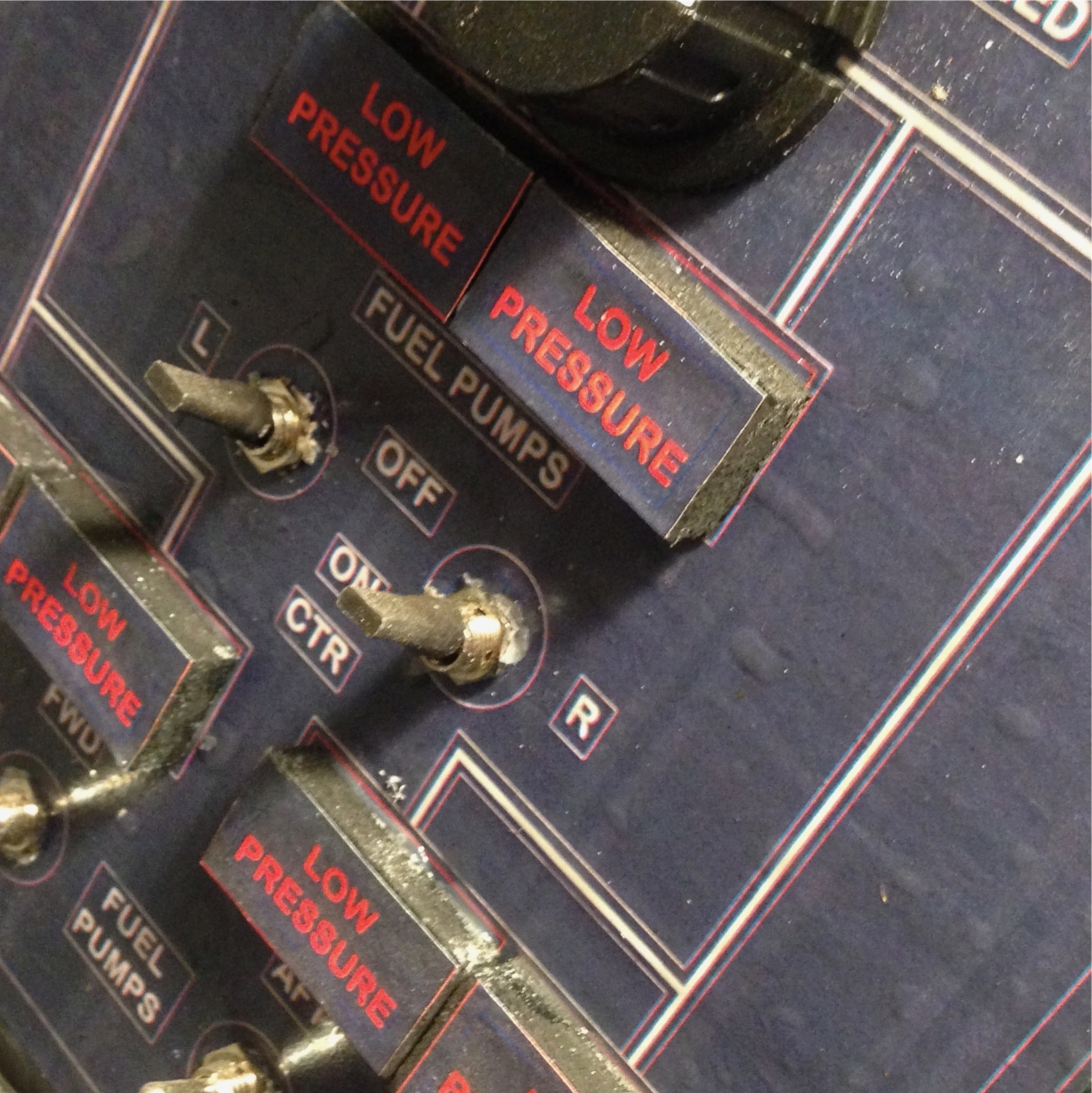
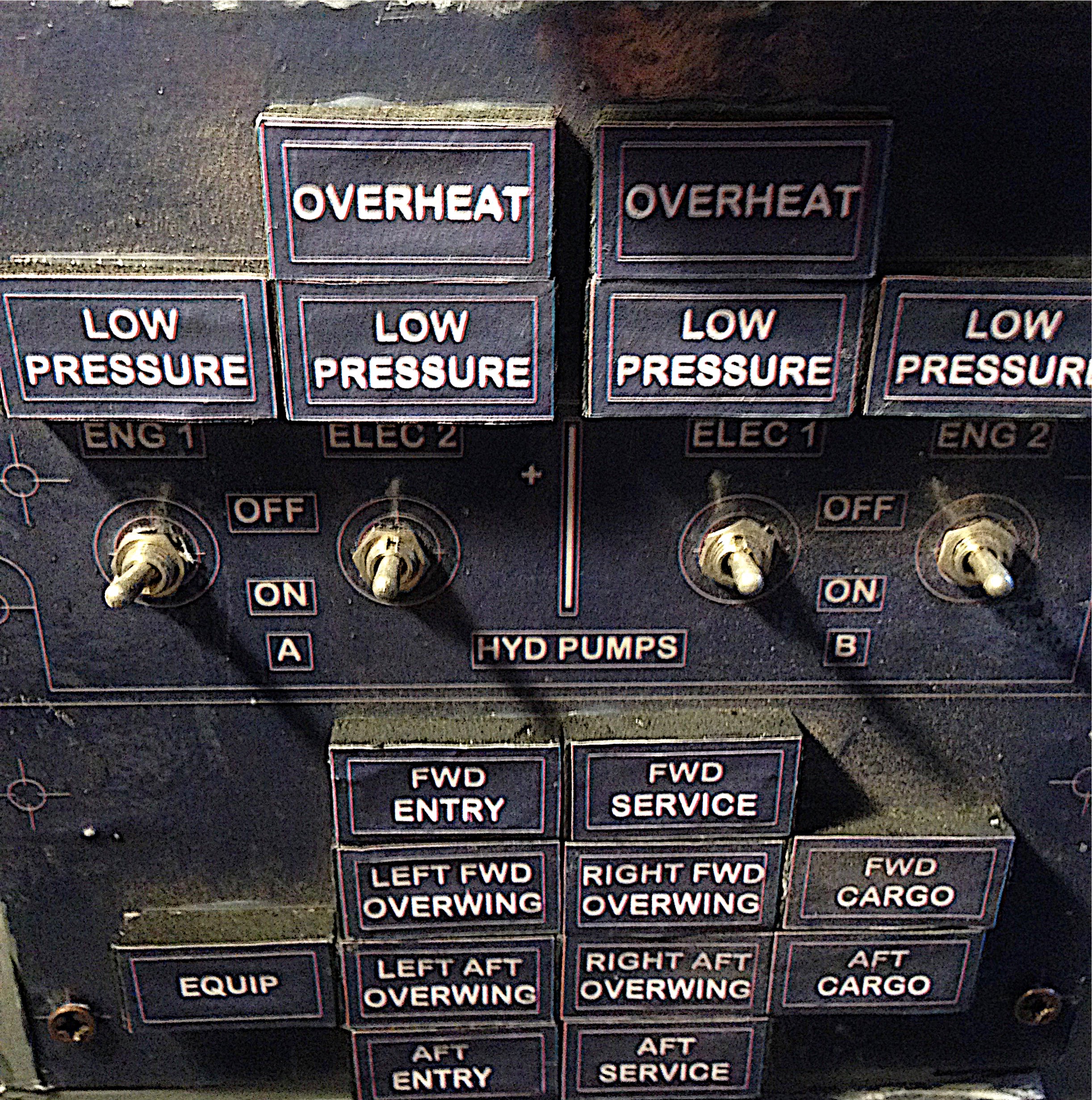
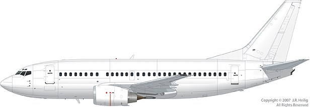
737-500 Flight Simulator cockpit

In these pages I will destails how I built (and am still building) a full 737 cookpit printing panels, connecting different components and orchestrating all those technologies with arduino microcontroller and software built to interface flight simulators with external sources

If you need additional specific information about this topic or if you want to look it personally please write an email

See it in action

Some Backgound

In 2010 I decided to build a boing 737 cockpit. In order to build the cockpit I selected Microsoft Flight Simulator as software because it was more compatible with interfaces and with devices available on the market. In order to read FSX parameters I then purchased a very interesting software called FSUIPC. It's a comms interface able to read and write FSX values. This interface has an SDK that can be used to develop connectors of every type to FSX. In order to speedup the development of the cockpit I decided to use a software already developed able to interface with electric components using a specific language. This software is SIOC based on SIOCP scripts. Due to the complexity of this language it was not very easy to start this project and at the beginning I was able to buld just few buttons able to interact with major fsx components (Battery, lights etc.) and the EFIS module. After some searches on internet I discovered many interesting components and decided for crgsim in order to display on two secondary monitors the efis, the maps and the engines status. Finally in 2015 I discovered Mobiflight. Mobiflight is an interesting opensource project which allow anyone to interface FSUIPC with an Arduino and potentially to all electric components needed to build a cockpit. Thanks to Mobyflight I was able to build the Autopilot unit and to complete the main cabin components

If you want to obtain very realistic results you cannot use FSX but need to use a more professional and supported software like Xplane

Xplane Logo

The problem with Xplane is that it doesn't interact with FSUIPC as FSX. Fortunatelly I found a similar plugin for Xplane called XPUIPC (you can find it in the Download Area).
XPUIPC emulates the same offset defined by Pete Dawson in his original library. Using these offsets you are able to intercept events raised from Xplane and you can raise events to Xplane to comunicate status changes of your hardware.
This can be done on the same computer running Xplane (in this case you need just xpuipc) or in a different computer directly connected to your hardware and where your control software is running.
In this second case you need somefing called wideClient which allow IPC communication over the local area network so to intercept offset also on remote computers.

In order to read offset messages you have two options. The first one is to build an IPC software and receive messages directly from XPUIPC or to use something already built for this pourpose like I did with Mobiflight
The following image (that you can find on the main web site) explains very well what you can implement using this software or any IPC software you can implement to read offsets)

Mobiflight

Throttle levers

Using a 3d printer I built a project found on Thingiverse. This project was very hard to implement as I was forced also to start using a cad (in my case Sketchup) in order to mirror the STL object used as throttle lever.

Throttle levers

I used also a push button installed for the toga function and an end stop buttoning order to activate reverse

Throttle lever in action
The following video describe Throttle components in action.

FCC (The Flight Control Computer)

The MCP is the Autopilot module. Togheter with the EFIS this module is used to flight an airplane following the flight plan and the tower indication. . This replica is the replica of a 737 NG MCP and has been built using Arduino 2560, the software Mobiflight. Push buttons have been purchased via interned from the Opencocpit web site.

The 7 segs displays are driven using MAX7219 following the schema reported here to connect multiple display in serial.

NOTE. In the picture is reported an Arduino uno. My MCP is built using a 2560 because Mobiflight works only using the 2560. However, connections are the same.

You will see that this picture is different from the one you can find in the Mobiflight Tutorial. This because the module used in the site explanation is a pre-built module already multiplexed and connected to the chip. The problem of the tutorial is that when you build a cockpit you do not need a module so big like the one in the explanation. You could need (for example) 4 digits for the altimeter and 4 digits for the left course but not 8 and 8. The number of digits you can display with a MAX module is so small (8 per module) that you cannot waste a module for each component.

For this reason you need different spare 7-Segs modules connected 8 by 8 to a max7219 module. Now the complex part of the game is that a Max7219 cannot be connected directly and contemporary to 8 single 7-segs displays but must be connected to a 'multiplexed' version of them. The concept of Multiplex is not so easy to explain and for this reason I prepeared a tutorial to explain you how to multiplex more than 1 7-Seg display using few pins to control more digits.
So, what is presented in my picture is the connection schema between Arduino and the MAX chip and between the chip and a 'multiplexed' version of 8 digits.
With the right cabling (this is up to you) you will be able to use these 8 digits separated to do what you need to do (for example 3 for the left course, 3 for the right course and 2 for the vertical speed).

Once you have used the first 8 digits you can cascade a second Max chip with other 8 digits to the first one and so on (it is not clearly specified in the picture but you can cascade more chips one after the other). As you can see in the mobiflight tutorial you can define many different digits depending on the pins available on the arduino mega you use. If you finish pins on your arduino you can use another arduino and continue again and again.

Before connecting cables

Testing using MobiFlight

Other components

In the following Carousel you will find a slideshow of many components. Each of them has been built using different tecniques improved during those years. Some of them have been built using Plexiglas and Led fixed on the back as backlight for the panel. Other panels have been built using 3d printed frames. In some cases I used also wood to build small frames and components

APU Panel

The APU is a source of bleed air and AC electrics for the aircraft, this gives independence during turnarounds, electrical backup in the event of engine failure and provides air conditioning & pressurisation during an engine bleeds off take-off. It's electrical power source is the battery, many series -500 aircraft have an extra, dedicated APU battery to preserve main battery usage.

Battery Panel

AC voltage and frequency may be read on the AC voltmeter and frequency meter for standby power, ground power, generator No. 1, APU generator, generator No. 2 and the static inverter.
Frequency is indicated only when the generator is electrically excited.
The voltage regulator automatically controls the generator output voltage. Current readings for the two engine IDGs and the APU generator may be read on the AC ammeter.
The TEST position is used by maintenance and connects the voltage and frequency meter to the power systems test module for selection of additional reading points.

EFIS

An electronic flight instrument system (EFIS) is a flight deck instrument display system that displays flight data electronically rather than electromechanically.
An EFIS normally consists of a primary flight display (PFD), multi-function display (MFD), and an engine indicating and crew alerting system (EICAS) display.
Early EFIS models used cathode ray tube (CRT) displays, but liquid crystal displays (LCD) are now more common. The complex electromechanical attitude director indicator (ADI) and horizontal situation indicator (HSI) were the first candidates for replacement by EFIS.
Now, however, few flight deck instruments cannot be replaced by an electronic display.

Fuel Pump Panel

The fuel panel is used to move fuel across different tanks and to make the fuel available to engines. It is also used to balance the aircraft moving the fuel in the right position.
different indicator analise pump pressure

Hydraulic pump Panel

The 737-500 had system A powered by the two Engine Driven Pumps (EDP's) and system B powered by the two Electric Motor Driven Pumps (EMDP's).
There is also a ground interconnect switch to allow system A to be powered when the engines are shut down.
From the 737-300 onwards each hydraulic system had both an EDP and an EMDP for greater redundancy in the event of an engine or generator failure.

Leave a Comment