Step 1: Extruder Removal
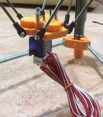
The first step involved carefully removing the original extruder assembly while maintaining the delta mechanism's integrity.
Converting a delta 3D printer into a powerful laser engraving system
Building on the success of the new Printerina 3D printer project, this modification transforms the compact delta printer into a versatile laser engraving system. By replacing the extruder with a 2500mW 445nm laser module, we've created what might be the first delta-based laser engraver.
The first step involved carefully removing the original extruder assembly while maintaining the delta mechanism's integrity.
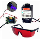
The 2500mW 445nm Laser Head Engraving Module was installed, featuring:
M106 S0
G92
G2
G1 X10 Y10 Z0
G4 P0
M106 S255
// ... calibration pattern ...
M106 S0
A special calibration pattern helps find the optimal focal height for maximum cutting efficiency.
If you have specific questions about this project, please send me an email or leave a comment. I will reply as soon as I will be available.
If you need additional information or have questions about this project, feel free to reach out: write an email.