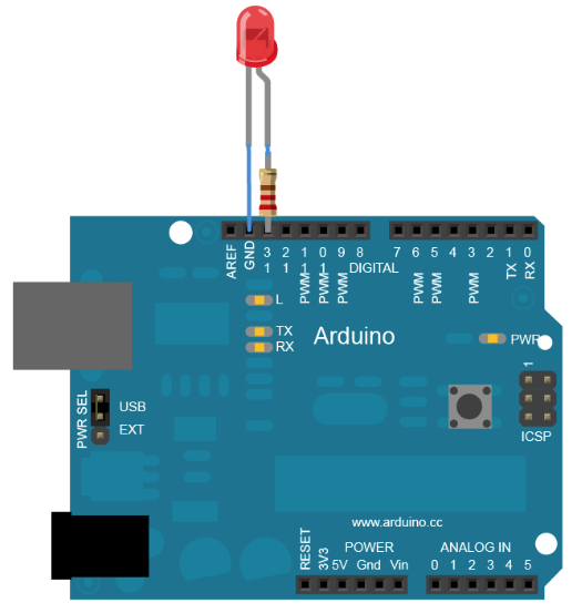
 In order to turn on or off a pin you need simply to put as HIGH the signal for that pin.
 Now that you have clear how to drive a led we can start considering a 7 segs digit
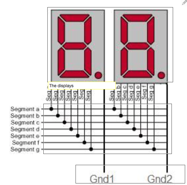
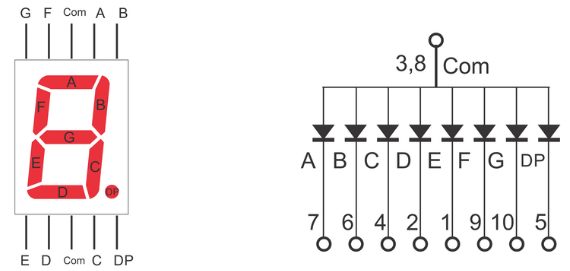 As you can also see from the electric schema, this component is nothing more than a group of 7 leds (diode) put together with a common pole, in this case the Anode. In fact, to be more detailed you can have two kind of seven segs digit.
The ones with common cathode and with common Anode .
As you can also see from the electric schema, this component is nothing more than a group of 7 leds (diode) put together with a common pole, in this case the Anode. In fact, to be more detailed you can have two kind of seven segs digit.
The ones with common cathode and with common Anode .
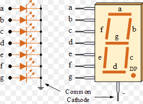 Now if you have 8 leds (the 8th is the comma) with a common pole (ground for example), how many Arduino PINS will you need to drive just a digit? The answer is very easy: you will need 8 digital pins plus the connection to the ground one.
Imagine now to connect 8 digits to an Arduino board (or any other logic controller. You will need 8*8+1 pins (65). As you can understand this can be very expensive and complex to implement.
Now if you have 8 leds (the 8th is the comma) with a common pole (ground for example), how many Arduino PINS will you need to drive just a digit? The answer is very easy: you will need 8 digital pins plus the connection to the ground one.
Imagine now to connect 8 digits to an Arduino board (or any other logic controller. You will need 8*8+1 pins (65). As you can understand this can be very expensive and complex to implement.For this reason, we use an approach called multiplexing. In few words, it means that you use the same 8 pins used for the first 8 leds plus the common anode or cathode to use as signal. So, if you have 4 digits you will use just 12 pins (7 for the number, 1 for the comma and 4 for the signal).
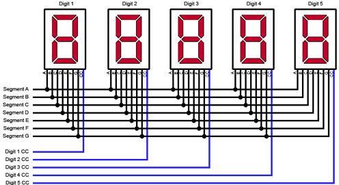 With this basic configuration, you can activate and deactivate the signal pin in order to switch on and off the digits in sequence. If you switch them on and off sequentially displaying different numbers on each digit and if the display frequency is higher than 30 MHz then you eyes
will not see the digit switched of but the persistence effect will mask the view and it will seems to you that you are properly display the entire number.
With this basic configuration, you can activate and deactivate the signal pin in order to switch on and off the digits in sequence. If you switch them on and off sequentially displaying different numbers on each digit and if the display frequency is higher than 30 MHz then you eyes
will not see the digit switched of but the persistence effect will mask the view and it will seems to you that you are properly display the entire number.
 It is time now to give a look at the code needed
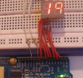
In the following code we will multiplexing a common cathode set of digits (-). This means that we will use the ground as control line. If ground is the common line you need to connect the two control lines not to ground but to two digital pin using a resistor to down the current sent by the positive pin
The code is really easy and has nothing to do with a real code needed to do useful stuff but it explain you very well the concept of multiplexing.
          int pin1 = 2;
          int pin2 = 3;
          int pin3 = 4;
          int pin4 = 5;
          int pin5 = 6;
          int pin6 = 7;
          int pin7 = 8;
          int gnd1 = 11;
          int gnd2 = 9;

          int timer = 1000;
          ipinMode(pin1, OUTPUT);
          pinMode(pin2, OUTPUT);
          pinMode(pin3, OUTPUT);
          pinMode(pin4, OUTPUT);
          pinMode(pin5, OUTPUT);
          pinMode(pin6, OUTPUT);
          pinMode(pin7, OUTPUT);
          pinMode(gnd1, OUTPUT);
          pinMode(gnd2, OUTPUT);
            //this represents the number "20"
          for (int i=0; i=timer-1; i++){
            digitalWrite(pin1, B1);
            digitalWrite(pin2, B1);
            digitalWrite(pin3, B0);
            digitalWrite(pin4, B1);
            digitalWrite(pin5, B0);
            digitalWrite(pin6, B1);
            digitalWrite(pin7, B1);
            digitalWrite(gnd1, B0);
            digitalWrite(gnd2, B1);

            delay(0.5);

            digitalWrite(pin1, B1);
            digitalWrite(pin2, B1);
            digitalWrite(pin3, B1);
            digitalWrite(pin4, B0);
            digitalWrite(pin5, B1);
            digitalWrite(pin6, B1);
            digitalWrite(pin7, B1);
            digitalWrite(gnd1, B1);
            digitalWrite(gnd2, B0);
            delay(0.5);

            }
Increase the number of digits (Adding more common cathod 7 segs display)
Increase the display time (timer)
Change the number displayed
Build a function to display a specific number (storing, for example, in an array the sequence of led to turn on for each specific number and creating a function based on the element of the array selected)
Create complex view or panels
The description contained in this tutorial should be used for simple stuff like a counter, a timer or similar stuff. If you need something more complex, I strongly suggest to use an external shift controller like the MAX7219. This component is the one I used to built my mcp (autopilot to run the 737-500 coockpit). In that specific case the digits connection is multiplexed but there is not any direct connection to arduino, so to not force arduino to control the whole logic of a muliplexing process.
Following this specific approach, arduino can be dedicated to other functions leaving to the external register the shifting work.