In the following picture, note the completed structure:
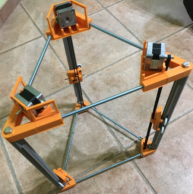 At the completed structure I fixed the motors that, as I previously said, will be placed in the head of the printer.
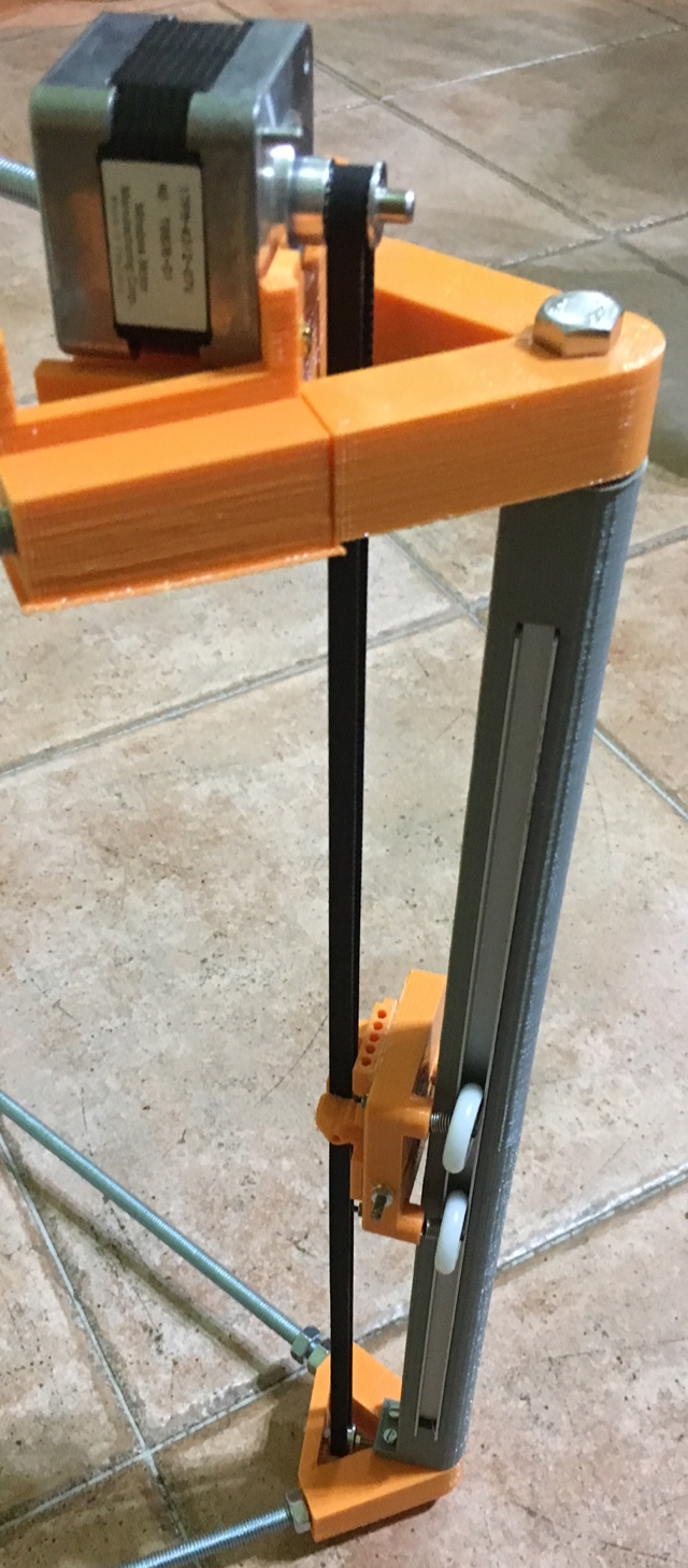
In this photo you will notice how I connected the first motor belt to the wheel at the base of the printer.
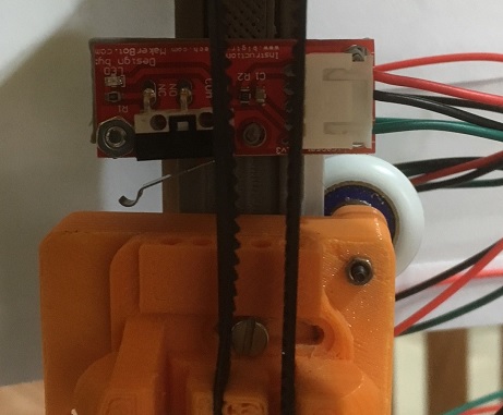
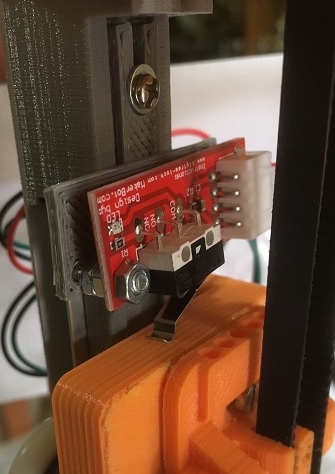
 After a couple of try, finally, I was able to print a perfect end-stop frame.
 For such similar printers I have always used digital endstops and this is what I did this time as well.
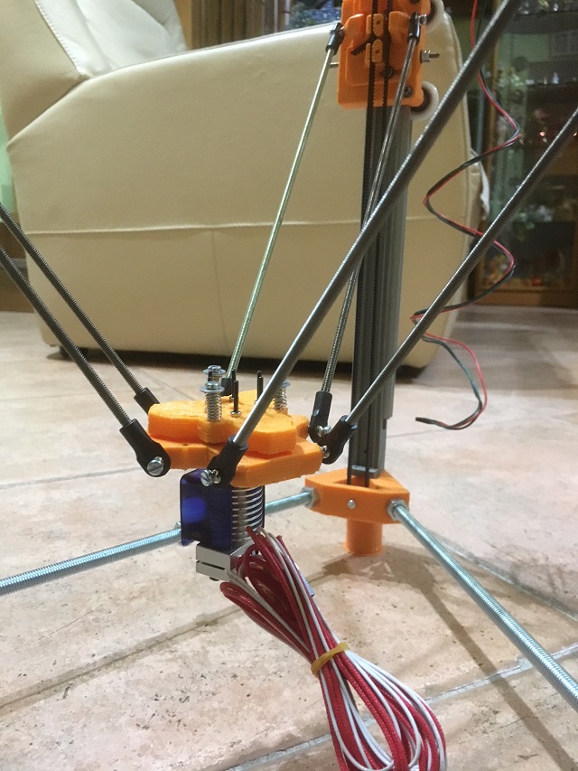
It is now time to start working to the extrusion. In order to build a stable head and to have the possibility to install a Z-Probe switch, after the initial printer setup, I decided to buld a classic small head carriage with a top hat connected using some springs.
those springs will support me at a later stage to installa an endstop to control the probe option.
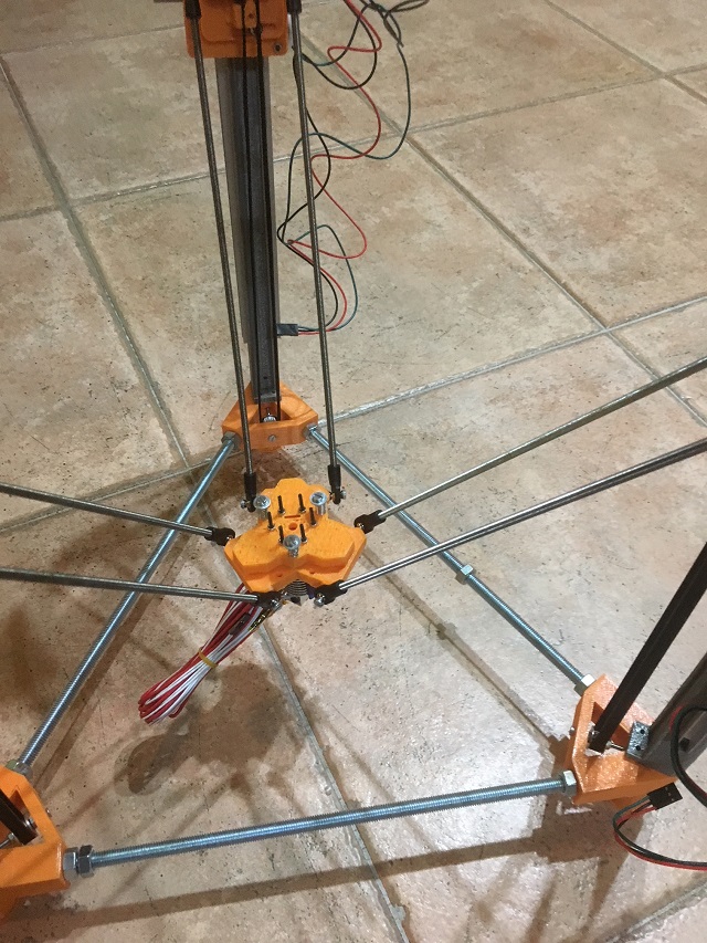
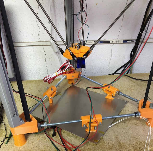
In the following picture you will see also the rod system I built connecting legs to the new heder effector. The effector is compatible with the classic J-Head standard
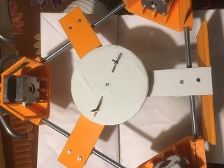
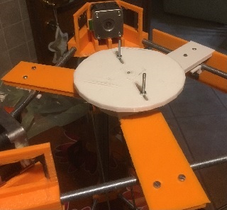
For this reason I decided to build an integrated top surface for the printer including:
1) A place where to install a stepper motor connected to the extruder
2) Something able to substain a reel of filament
Probably the term "substain" is not exactly the right one. In this case the idea is to find a way to build something who can also provide the filament to the stepper motor when requested. For this reason I used some bearing wheels and built a rotating plate able to substain the filament but also to rotate giving the requested filament to the extruder.
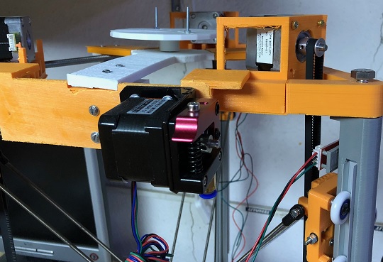 To increase the height of the printable area, without to interfere with the total height of the printer (don't forget that the target for this printer is to be minimal in terms of dimension), I decided to create a special support for the plate. The plate is now not sustained from the
back but it is in the lower possible solution. This result has been obtained creating some specific supports and additional holes in the aluminum plate. In the following picture, you will see how it fits with the printer chassis
To increase the height of the printable area, without to interfere with the total height of the printer (don't forget that the target for this printer is to be minimal in terms of dimension), I decided to create a special support for the plate. The plate is now not sustained from the
back but it is in the lower possible solution. This result has been obtained creating some specific supports and additional holes in the aluminum plate. In the following picture, you will see how it fits with the printer chassis
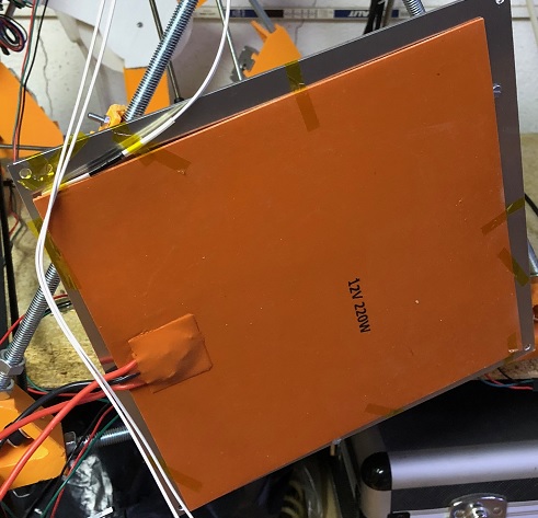
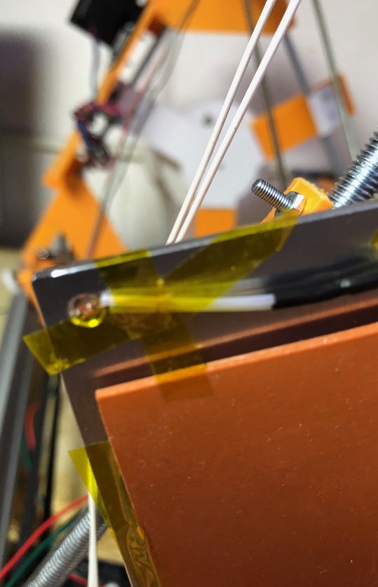
 Because I did never use it, I decided to test a silicon plate to heat the bed of this printer. I know this is not very common and not very easy to install but I found interesting tutorials on how to do it and in the near future I will draw a schema for you also.
To install it you need to use a solid-state relay named SSR. This relay is activated by the Arduino board (I use RAMP 1.4) and allow the right current to go to the plate. However, the current can come from any available source depending on the kind of silicon plate you buy (12, 24 or 220V).
To attach it to the aluminum plate I used some red silicon and some high temperature adhesive.
In the two pictures below, you will see a detail of the silicon plate connected to the aluminum one and a view of how I installed the thermistor used to read the temperature of the plate. This thermistor activates the RAMP 1.4 exit PIN will drive the SSR, which will allow (or not) the current to reach the plate.
Because I did never use it, I decided to test a silicon plate to heat the bed of this printer. I know this is not very common and not very easy to install but I found interesting tutorials on how to do it and in the near future I will draw a schema for you also.
To install it you need to use a solid-state relay named SSR. This relay is activated by the Arduino board (I use RAMP 1.4) and allow the right current to go to the plate. However, the current can come from any available source depending on the kind of silicon plate you buy (12, 24 or 220V).
To attach it to the aluminum plate I used some red silicon and some high temperature adhesive.
In the two pictures below, you will see a detail of the silicon plate connected to the aluminum one and a view of how I installed the thermistor used to read the temperature of the plate. This thermistor activates the RAMP 1.4 exit PIN will drive the SSR, which will allow (or not) the current to reach the plate.