Introduction
During the pandemic crisis in winter 2020, I miss so much my RV that I decided to build something to support people who were building their own RV. For this reason, I decided to start investigating how to build (using Arduino) an RV control unit.
Obviously, I am mentioning RV but it could be used for caravans, campers and so on, with no limit to the fantasy. It just requires a 12V input and can produce a controlled output to use with your devices.
Important Safety Notice: I will not be responsible for any damage you will cause building such equipment on your own. If you are not expert with electricity or with batteries, please stop thinking to proceed with this project. Car and RV batteries are batteries who can produce a high amount of current and this could cause problems (fire, shock etc.)
Project Scope: Even if I will try to build something more sophisticated, this project cannot be considered a professional one. Professional control units have different nodes communicating each other with special protocols while this CU is controlled just by one arduino and by different physical switches and sensors. However, if you need just to turn on and off light and have your water pump working, this project could be your one.
Front Panel
First, give a look at the front panel:
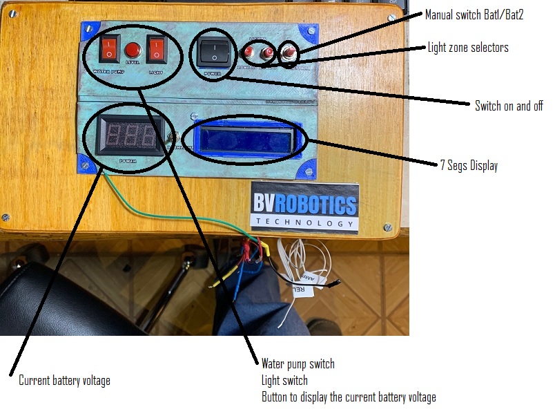
Let me start saying that the panel is made of wood with a plastic panel fixed to it with 4 screws. I draw the plastic panel using sketchup and printed it with my printerina printer. If you need it and want to download the STL files, you can follow this link to the MakerWorld project page.
As you can see, I used different buttons, switches and push buttons to control all sections. There is also a 7segs display (2 lines) used to display user informations.
On the left side, there is a 2-digit voltmeter. To save energy the volt meter will be active only upon request (pressing the button at the bottom). I evidenced in the picture all the functions implemented for this control unit.
Control Functions
Starting from the left bottom:
- Battery Management: This device can combine two batteries, switching between one or another based on the voltage. Lower is the voltage less is the possibility that a specific battery is selected. However, the control unit will switch between the two batteries to, constantly, display the voltage so you will have one battery selected but both voltages displayed every 10 seconds (if the display is active).
- Control Activities: A section (top left) dedicated to the control activities. From here you are able to activate or deactivate the water pump (it will give current to the pressure-switch), the lights (we will see in the next item how to differentiate between the 2 zones) and a button to check levels (those values will be displayed on the 7 segs control panel).
- Power Control: Top Centre there is a button to switch on and off the control unit.
- Light Zones: To split the light compartment in two zones I used 2 push buttons (Top Right). Pushing those buttons, you can activate or deactivate a zone. There are 2 zones and the activation or the deactivation is displayed on the LCD panel.
- Battery Selection: The logic implemented in the firmware automatically perform a switch between the two batteries when the active one reach a lower level. This allow the two batteries to be used at the same time in the same way. However, if the user want to switch manually from a battery to another there is on the right (top) a 3-position switch. Moving the switch in the middle, the system decides autonomously what to do. If you move the switch on Battery A or on Battery B then the control unit deactivate the logic algorithm and activate the specified battery permanently. In the next version of the firmware, I will implement a sort of "protection logic" that will reactivate the auto switch in case the selected battery voltage goes under 12 V. I will need to implement also something to switch off automatically the central unit when both battery are under a certain V threshold.
- Display: I used a simple 7Segs display to show the status of the system (objects turned on, sections and battery level). I preferred a 7 segs display for two main reasons. The firmware is heavy and faster because you do not need an external library to drive the LCD panel and because the power needed, is less. However, in a future version we could also decide to use an LCD panel and display in a graphical way all items.
Sensor Unit
Now let's move to the sensor unit (Arduino is connected directly to the panel while the sensor box is separated to avoid any interference generated by the Arduino clock).
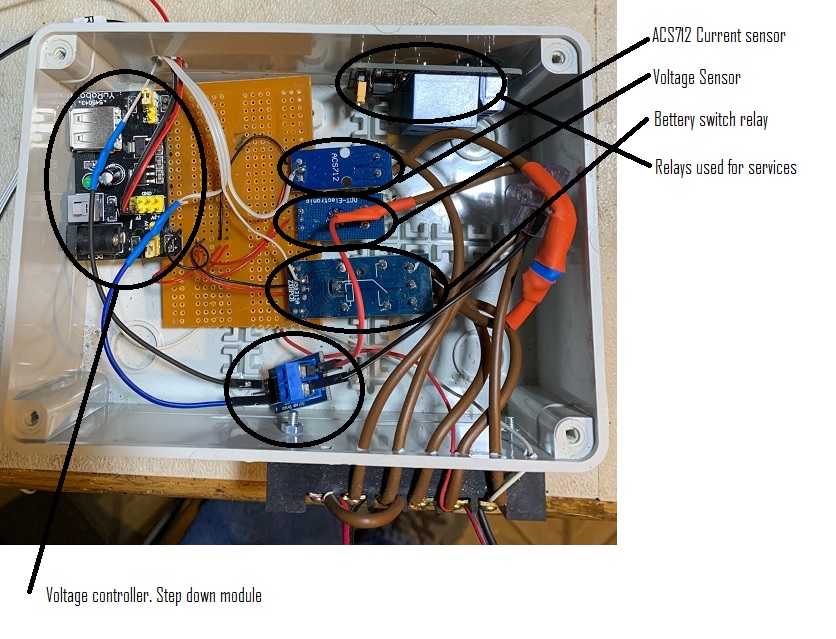
In this unit, I concentrated the sensors used and the actuators (relays). As you can see there is/are:
- Voltage Controller: A voltage controller used to validate the voltage of any single battery. Each battery is switched by the relay and connected (every X seconds) to the voltage meter who evaluate the voltage of the battery (Note that this component must be connected to an analogic port of Arduino).
- Battery Relay: A relay connected to both batteries and to the voltage regulator. The switch happens constantly every 10 seconds to allow Arduino firmware to evaluate the voltage of the battery.
- Current Meter: A current meter positioned at the end of the circuit measuring the output current sent to the internal RV circuit.
- Control Relays: Some relays to switch on and off the water pump and the two light zones.
Source Code
Now it is simply the time to give a look at the source code made for Arduino. In the code there are different time cycles using the millis() command. The most important one is the one I built to check the status of the batteries:
Battery Check Logic
if (((millis() - BatteryCheckTimer) > BatteryInterval) && !batterySelected) {
    value = analogRead(PinBatt);
    vout = (value * 5.0) / 1024.0; // see text
    vin = vout / (R2 / (R1 + R2));

    if(vin < 12) {
            sprintf(VoltChar, "LOW" );
    }
    else {
        sprintf(VoltChar, dtostrf(vin, 2, 2, "%f" ));
        Serial.print("VoltChar:");
        Serial.println(VoltChar);
        VoltChar[5]='\0' ;
    }

    //Switch to BatteryB
    if (ReleStatus == LOW) {
        analogWrite(PinBatRel, 255);
        ReleStatus = HIGH;	//Battery2
        BAT2val[0] = '\0';
        sprintf(BAT2val, "%s", VoltChar);

        if (BatteryInterval == 1500)
            BatteryInterval = 20000;
    }
    else
    {
        analogWrite(PinBatRel, 0);
        ReleStatus = LOW;		//Battery 1
        BAT1val[0] = '\0';
        sprintf(BAT1val, "%s", VoltChar);
    }

    sprintf(BatteryNextMessage, "B1:%sB2:%s", BAT1val,BAT2val);
    Serial.println(BatteryNextMessage);
    BatteryMessage = true;
    BatteryCheckTimer = millis();
}
Once the interval "arrives", we switch the battery and read the Voltage value. The voltage meter used is nothing more than a tension splitter. It splits the Vin in a value that can be read by an analogic pin in Arduino splitting the voltage in a value between 0 a 1024. Obviously you need to report this value to 12 volts so the formula to use will be:
vout = (value * 5.0) / 1024.0;vin = vout / (R2 / (R1 + R2));
If the switch is active then the value must never be less than 12V. Once the value is read, then a message is stored in a variable (BatteryNextMessage) and this variable is displayed using another timer in the LCD display:
Display Update
if(BatteryMessage == true) {
    lcd.cursorTo(1, 0);
    lcd.printIn("                ");
    lcd.cursorTo(1, 0);
    lcd.printIn(BatteryNextMessage);
    BatteryMessage = false;
}
Button Reading
Another interesting part of the code is when (another timer) the system read the buttons values:
if((millis()-PrintTime)>1000) {
    //ReadButtons
    int LightCircuitPower = digitalRead(PinLightOn);
    int WaterCircuitPower = digitalRead(PinWaterOn);
    int LightZone1Power = digitalRead(PinLightZone1);
    int LightZone2Power = digitalRead(PinLightZone2);
    int LevelSwitch = digitalRead(PinLevel);
    int BatASwitch = digitalRead(PinBatASwitch);
    int BatBSwitch = digitalRead(PinBatBSwitch);
}
Once those values have been read a cycle is executed for each single function and the relay is activated or deactivated. For example, here you will find the water pump circuit:
Water Pump Control
if (WaterCircuitPower != PrevWaterCircuitPower) {
PrevWaterCircuitPower = WaterCircuitPower;
if (WaterCircuitPower == LOW)
{
sprintf(NextMessage, "Water pump On");
PrintMessage = true;
digitalWrite(PinWaterPumpRele, HIGH);
}
else
{
sprintf(NextMessage, "Water pump Off");
PrintMessage = true;
digitalWrite(PinWaterPumpRele, LOW);
}
Serial.print("WaterCircuitPower:");
Serial.println(WaterCircuitPower);
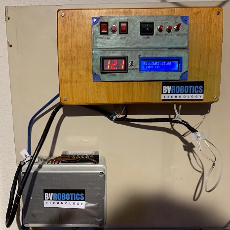
}Final Result
Once completed and assembled the aspect of the control unit is also very clean and simple. Here in a picture while wall mounted in my garage:
Need More Information?
If you have specific questions about this source code or this project, please send me an email or leave a comment. I will reply as soon as I will be available.
If you need additional specific information about this topic or if you want to look it personally please write an email.